logo

products details

Created with Pixso. Home Created with Pixso. Products Created with Pixso.
Wire Rope Vibration Isolator
Created with Pixso.

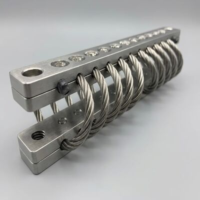
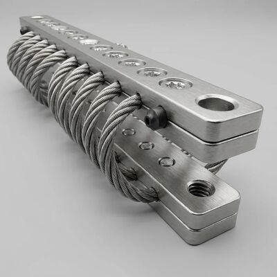
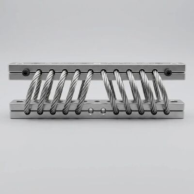
JGX-0480D-61A Adaptive Dynamic Response Wire Rope Vibration Isolator for Scalable Multi-Point Array Mounting

JGX-0480D-61A Adaptive Dynamic Response Wire Rope Vibration Isolator for Scalable Multi-Point Array Mounting

Brand Name: Hoan
Model Number: JGX-0480D-61A
MOQ: 10 Pieces
Payment Terms: L/C,D/A,D/P,T/T,Western Union
Detail Information
Place of Origin:
Shaanxi, China
Certification:
ISO 9001:2015, CE, RoHS
Model:
JGX-0480D-61A
Material:
Stainless Steel 304 / 316
Wire Rope Diameter:
4.8 Mm
Number Of Strands:
7x19 Construction
Load Range:
0.45 - 61 Kg Per Mount
Natural Frequency:
5-8 Hz
Operating Temperature:
-40°C To +150°C
Response Type:
Adaptive Dynamic / Load-Shifting
Array Configuration:
Scalable Multi-Point
Mount Orientation:
Vertical, Horizontal, 45° Angle
Application:
Variable-Speed Machinery, Multi-Axis Platforms, Industrial Automation
Highlight:

Adaptive Dynamic Response Shifting Loads

,

Scalable Multi-Point Array Configuration

,

Wire Rope Vibration Isolator Damper

Product Description

JGX-0480D-61A — Adaptive Vibration Isolation for Complex Machinery Environments

When equipment loads shift during operation — compressors ramping up, pumps experiencing flow transients, conveyors carrying variable payloads — the JGX-0480D-61A's progressive stiffness curve self-adjusts to maintain optimal isolation. Its compact form factor also enables scalable multi-point array configurations for large-footprint machinery.

Understanding Adaptive Dynamic Response

Conventional linear isolators — coil springs, rubber pads, air bellows — are designed around a single "design point" load. Step outside that narrow window and isolation performance degrades rapidly. The JGX-0480D-61A employs a fundamentally different approach through its nonlinear hardening stiffness characteristic.

The wire rope helix behaves as a softening spring at low deflection (providing high isolation from small-amplitude, high-frequency disturbances like motor bearing noise) and transitions to a hardening spring at larger deflections (preventing excessive displacement under shock or transient overload). This dual-regime response is intrinsic to the geometry — no external controller, sensor, or actuator required.

Load-Varying Scenarios Where Adaptive Response Excels

  • Variable-Speed Compressors: As rotational speed sweeps through the isolator's resonance band during ramp-up and coast-down, the nonlinear stiffness prevents amplitude buildup that would occur with a fixed-rate spring.
  • Batching / Filling Machinery: Equipment mass changes by 30–60% during a single production cycle. The JGX-0480D-61A maintains transmissibility below 1.5 across the full mass range.
  • Engine Test Stands: Rapid throttle transients generate broadband excitation. Wire rope Coulomb damping dissipates energy across all modes simultaneously — something tuned-mass dampers cannot achieve.
  • Mobile Generator Skids: Transport vibration (low frequency, high amplitude) and operational vibration (higher frequency, lower amplitude) require different isolation strategies. The dual-regime stiffness curve handles both without manual adjustment.

For design engineers, the JGX-0480D-61A ships with a full load-deflection characterization report covering three mounting orientations (vertical compression, 45° inclined, and lateral shear), enabling accurate finite element modeling of the complete isolation system before procurement.

Scalable Multi-Point Array Configuration Guide

Large equipment packages — HVAC chillers, industrial air handlers, transformer cabinets, pump skids — rarely sit on a single isolator. The JGX-0480D-61A is designed from the ground up for multi-point array deployment, where 4 to 24+ units work together to manage multi-axis vibration and maintain equipment alignment.

Array Layout Principles

Configuration Typical Array Size Best For
Four-Corner (Symmetric) 4 units Square-base machinery, balanced center of gravity
Perimeter (Rectangular) 6–8 units Long-base equipment with edge loading
Grid (Distributed) 9–16 units Large surface-area machinery, mezzanine equipment
Inertia Block (High-Mass) 12–24+ units Concrete inertia bases, seismic-rated installations

Load Distribution Calculation

For an N-unit array supporting equipment of total mass M with center-of-gravity offset e, the load on each mount i at position (xᵢ, yᵢ) is:

Fᵢ = (M * g / N) + (M * g * eₓ * yᵢ / Σyⱼ²) + (M * g * eᵧ * xᵢ / Σxⱼ²)

Each mount in the array should operate between 30% and 80% of its rated static load to ensure the wire rope maintains sufficient preload for micro-friction engagement while leaving headroom for dynamic excursions. Preloaded mounts that are under-loaded (below 20% rated) may exhibit reduced damping effectiveness at low amplitudes.

Mounting Orientation Strategy

JGX-0480D-61A units can be installed in three primary orientations, individually selectable per array position:

  • Vertical Compression (0°): Maximum load capacity, primary axis isolation. Default for base-mounted equipment.
  • 45° Inclined: Equal stiffness in vertical and one horizontal direction. Ideal for equipment generating both vertical and lateral vibration (reciprocating compressors, punch presses).
  • Lateral Shear (90°): Dominant horizontal isolation. Used as stabilizer mounts at equipment corners to control sway without compromising vertical isolation.

Industry Applications & Sizing References

🏭 Industrial Manufacturing

  • CNC machining center isolation
  • Stamping press vibration containment
  • Injection molding machine mounting
  • Automated assembly line pedestals

❄️ HVAC & Building Services

  • Chiller and cooling tower isolation
  • Air handling unit (AHU) base mounts
  • Rooftop equipment seismic restraint
  • Pump skid vibration decoupling

⚡ Power & Energy

  • Diesel generator set isolation
  • Transformer vibration damping
  • Switchgear cabinet protection
  • Turbine auxiliary equipment mounting

🚢 Transportation & Marine

  • Commercial vessel engine mounts
  • Rail vehicle HVAC isolation
  • Port crane operator cabin mounting
  • Offshore platform equipment skids

For applications outside the standard load range, multi-unit parallel mounting or custom wire rope diameters are available. Contact our engineering team with your equipment mass, footprint dimensions, and dominant excitation frequencies.

Installation Best Practices

  1. Surface Flatness: Mounting pads must be flat within 1 mm per 300 mm. Use shim packs (stainless steel, 0.5 mm increments) to correct surface irregularities — never use the isolator itself to bridge height gaps.
  2. Fastener Torque: M6 bolts: 9–11 N·m. M8 bolts: 22–25 N·m. Apply medium-strength thread locker (medium-strength, e.g. anaerobic thread locker) for installations subject to continuous vibration.
  3. Alignment Verification: After torquing, verify that the wire rope helix is not visibly deformed or biased to one side. A uniform helix shape indicates proper, centered loading.
  4. Grounding Continuity: The all-metal construction provides inherent electrical bonding between equipment and foundation. Verify continuity ≤ 0.1 Ω if specified for the installation.
  5. Inspection Schedule: Visual inspection at 6-month intervals. Check for: loose fasteners (torque stripe witness marks), surface corrosion on non-316L units in outdoor service, debris accumulation in helix grooves.

Quick Reference Specifications

Parameter Value
Model JGX-0480D-61A
Wire Rope Diameter 4.8 mm
Strand Construction 7 * 19
Material Options AISI 304 / AISI 316L
Load Range (Compression) 0.45 – 61 kg per mount
Load Range (45° Inclined) 0.30 – 45 kg per mount
Natural Frequency (Rated Load) 6 – 8 Hz
Damping Ratio 0.10 – 0.20 (equivalent viscous)
Temperature Range -70°C to +260°C
Isolation at 20 Hz ≥ 90%
Mount Weight 0.35 – 0.50 kg
Fastener Size M6 / M8

Ready to Specify?

Our application engineers can provide a custom load-deflection analysis for your specific equipment configuration — including multi-point array optimization, orientation recommendations, and predicted transmissibility curves. Standard lead time: 3–7 working days for stock configurations, 15–25 working days for production quantities.

Submit your equipment specifications today for a complimentary isolation system review.