| Brand Name: | Hoan |
| Model Number: | JGX-0648D-56A |
| MOQ: | 10 Pieces |
| Payment Terms: | L/C,D/A,D/P,T/T,Western Union |
When machinery loads fluctuate during operation — variable-speed drives ramping through resonance, batch processing equipment changing mass mid-cycle, mobile generator skids transitioning between transport and operational modes — the JGX-0648D-56A's nonlinear progressive stiffness curve self-adjusts to maintain optimal vibration isolation. Its 6.4mm wire rope diameter and compact footprint also enable scalable multi-point array configurations for large-footprint industrial equipment packages.
Conventional linear isolators — coil springs with fixed spring rates, rubber pads with single-durometer compounds, pneumatic air bellows with regulated pressure — are designed around one nominal "design point" load. Step outside that narrow operating window, and isolation performance degrades rapidly: transmissibility increases, resonance shifts into the operating speed range, and structural vibration amplifies rather than attenuates.
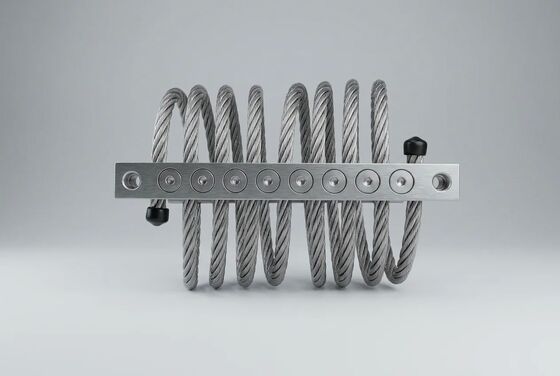
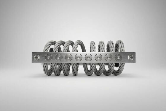
The JGX-0648D-56A employs a fundamentally different mechanical approach through its nonlinear hardening stiffness characteristic, an emergent property of the helically wound wire rope geometry itself. At low deflections (small vibration amplitudes), the rope helix behaves as a softening spring, providing high isolation efficiency against high-frequency disturbances such as electric motor bearing noise and pump impeller blade-pass excitation. At larger deflections (shock, transient overload, startup/coast-down through resonance), the stiffness transitions to a hardening regime, preventing excessive displacement while maintaining the wire rope within its elastic range.
This dual-regime response is entirely passive and intrinsic — no electronic controller, no feedback sensor, no pneumatic or hydraulic actuator. It is a geometric property of the helically wound wire rope, validated and repeatable across every production unit.
For design and simulation engineers, the JGX-0648D-56A ships with a full load-deflection characterization report covering all three standard mounting orientations (vertical compression, 45° inclined, and lateral shear). This data set — typically 30–50 measurement points per orientation — enables accurate finite element modeling of the complete isolation system within ANSYS, Abaqus, or COMSOL before procurement commitment.
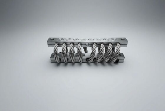
Large industrial equipment — HVAC chillers spanning 3–6 meter footprints, industrial air handlers weighing several hundred kilograms, transformer cabinets, multi-pump skid assemblies — cannot be isolated with a single mount. The JGX-0648D-56A is purpose-engineered for multi-point array deployment, where 4 to 24+ individual units are coordinated to manage multi-axis vibration while maintaining precise equipment alignment and uniform load sharing.
| Configuration | Array Size | Total Capacity | Primary Application |
|---|---|---|---|
| Four-Corner (Symmetric) | 4 units | Up to 224 kg | Square footprint machinery with balanced center of gravity |
| Perimeter (Rectangular) | 6–8 units | Up to 448 kg | Elongated equipment frames with distributed edge loading |
| Grid (Distributed) | 9–16 units | Up to 896 kg | Large surface-area machinery and mezzanine-level equipment |
| Inertia Block (High-Mass) | 12–24+ units | 1,300+ kg | Concrete inertia bases with seismic restraint requirements |
For an N-mount array supporting equipment of total mass M with known center-of-gravity coordinates (ex, ey) relative to the array geometric center, the static load on each individual mount i positioned at coordinates (xi, yi) is calculated as:
Fi = (M · g / N) + (M · g · ex · yi / Σyj²) + (M · g · ey · xi / Σxj²)
For optimal damping engagement and service life, each JGX-0648D-56A in the array should operate between 30% and 80% of its rated static load (approximately 17–45 kg per mount in vertical compression orientation). Units loaded below 20% of rated capacity may exhibit reduced Coulomb damping effectiveness at low vibration amplitudes, as the inter-strand contact pressure is insufficient to develop the full friction force. For applications with highly uneven load distribution, hybrid arrays combining different wire rope diameters can be specified.
JGX-0648D-56A units can be individually oriented at each array position to match the dominant vibration direction at that location:
For equipment operating outside the standard 0.50–56 kg per-mount load range, parallel mounting of multiple JGX-0648D-56A units at individual attachment points or custom wire rope diameter configurations are available upon request. Contact our application engineering team with equipment mass, footprint dimensions, center-of-gravity coordinates, and dominant excitation frequencies for a tailored recommendation.
| Parameter | Value |
|---|---|
| Model | JGX-0648D-56A |
| Wire Rope Diameter | 6.4 mm |
| Strand Construction | 7 * 19 (133 wires total) |
| Material Options | AISI 304 / AISI 316L |
| Load Range (Vertical Compression) | 0.50 – 56 kg per mount |
| Load Range (45° Inclined) | 0.35 – 42 kg per mount |
| Load Range (Lateral Shear) | 0.25 – 28 kg per mount |
| Natural Frequency (at Rated Load) | 6 – 8 Hz |
| Equivalent Viscous Damping Ratio | 0.10 – 0.20 |
| Dynamic Amplification at Resonance | ≤ 4.0 |
| Temperature Range | -40°C to +150°C |
| Isolation at 20 Hz / 30 Hz | ≥ 90% / ≥ 95% |
| Mount Weight | 0.50 – 0.70 kg |
| Fastener Size / Torque | M8 (22–25 N·m) / M10 (42–48 N·m) |
Our application engineering team provides complimentary pre-procurement isolation system analysis for qualified projects — including multi-point array load distribution calculations, mounting orientation optimization, predicted transmissibility vs. frequency curves, and equipment-specific recommendations. Standard product lead time: 3–7 working days for stock configurations (AISI 304, standard bolt pattern), 15–25 working days for production quantities or AISI 316L specifications.
Submit your equipment specifications, GA drawing, and operating conditions for a no-obligation vibration isolation assessment.