| Brand Name: | Hoan |
| Model Number: | JZP-2.5C |
| MOQ: | 4 Pieces |
| Payment Terms: | L/C,D/A,D/P,T/T |
JZP-2.5C Rubber Shock Absorber — Product Overview
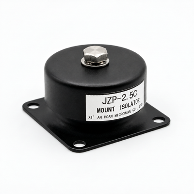
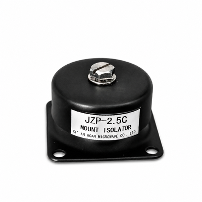
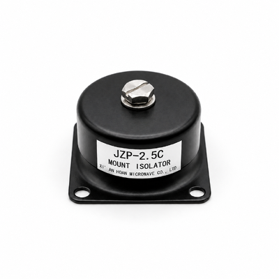
The JZP-2.5C is a prefabricated vibration isolator (JZP) in the JZP-C series, supplied by Xi'an Hoan Mirowave Co. Ltd. It is fitted between a vibrating machine and its base, or between a structure and its foundation, so that vibration and structure-borne noise are reduced before they reach the supporting frame. A rubber elastomer is bonded to metal plates, the unit is fixed with M4*10 screws, and it carries a nominal load of 2.5 Kg in a cylindrical body.
Why vibration and noise control matters
Left unchecked, vibration passes from a source into the surrounding structure, where it can loosen fasteners, fatigue joints and radiate noise into occupied spaces. An isolator interrupts that path and protects the machine, the structure and the people nearby. The JZP-2.5C is made to do exactly that in bridges, rail systems, buildings and industrial plant.
Technical parameters
| Technical Parameter | JZP-0.3C | JZP-0.5C | JZP-0.8C | JZP-1.0C | JZP-1.2C | JZP-1.5C | JZP-1.8C | JZP-2.0C | JZP-2.5C | JZP-3.0C |
| Pz Nominal Load (Kg) | 0.3 | 0.5 | 0.8 | 1.0 | 1.2 | 1.5 | 1.8 | 2.0 | 2.5 | 3.0 |
| Deflection | Downward Pressure | |||||||||
| Deformation Displacement (mm) | ≤0.3 | |||||||||
| Resonant Frequency (Hz) | 35±3 | |||||||||
| Working Temperature (°C) | -45~+65 | |||||||||
| Shock (Ks) | 100g / 6ms | |||||||||
| Peak Response (G) | ≤3.6 km/s2 | |||||||||
| Vibration (Kv) | Accord with National Standard GJB150-16 | |||||||||
![]()
![]()
Key specifications at a glance
Nominal load 2.5 Kg; natural frequency 7 Hz to 15 Hz; axial stiffness 50 N/mm; vibration isolation up to 90%; compression 1.6 mm; mounting hole size 5 mm; screw M4*10; cylindrical body.
Compliance and testing
Units are produced under an ISO9001:2015 quality system, and the vibration behaviour aligns with National Standard GJB150-16.
Customization options
The JZP-C family is built for custom design. Load capacity, stiffness and mounting details can be adapted to suit a given machine, structure or track, and prototypes can be produced quickly for evaluation.
Selection and installation notes
Match the model to the weight carried by each mounting point. Keep the mounting surface flat and rigid so the load is shared evenly, use the M4*10 screws and the recommended torque, and leave clearance for movement. Confirm the working temperature range before fitting the unit in an extreme environment.