logo

products details

Created with Pixso. Home Created with Pixso. Products Created with Pixso.
Rubber Shock Absorber
Created with Pixso.

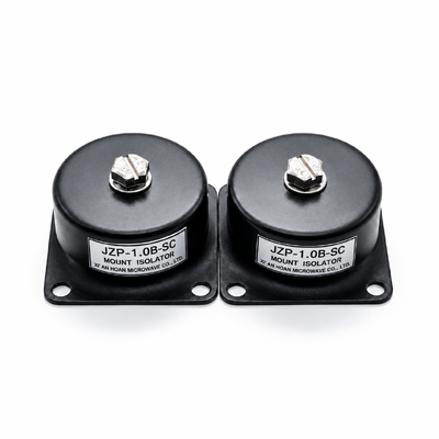
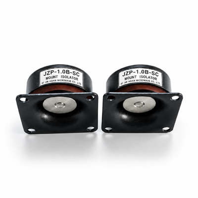
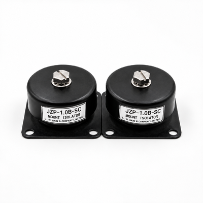
JZP-1.0B-SC Rubber Shock Absorber 46mm Body 30mm Height 100G Shock Rating 0.3mm Deflection

JZP-1.0B-SC Rubber Shock Absorber 46mm Body 30mm Height 100G Shock Rating 0.3mm Deflection

Brand Name: Hoan
Model Number: JZP-1.0B-SC
MOQ: 4 Pieces
Payment Terms: L/C,D/A,D/P,T/T
Detail Information
Place of Origin:
Shaanxi, China
Certification:
ISO9001:2015
Free Height:
30 Mm +/-1
Hole Centre Distance:
40 Mm +/-0.2
Foot Width:
50 Mm +/-0.3
Elastomer Hardness:
45-70 Shore A
Construction:
Natural Rubber Bonded To Steel Insert
Qualified Direction:
Vertical Compression
Storage Validity:
8 Years
Highlight:

High-Frequency Ripple Micro-Vibration Isolation

,

Fail-Safe Anti-Off Interlock Design

,

Extreme Load Rubber Shock Absorber

Product Description
JZP-1.0B-SC Rubber Shock Absorber 46mm Body 30mm Height 100G Shock Rating 0.3mm Deflection
JZP-1.0B-SC

Rubber Shock Absorber · JZP-B-SC series · Xi'an Hoan Microwave Co., Ltd. · Shaanxi, China · ISO9001:2015

In one paragraph: the JZP-1.0B-SC isolates the vibration that specifications usually ignore — high-frequency ripple and micro-motion that leaks past stiff mounts and reaches sensors and optics as noise. Its rubber element is mechanically captured by the bonded insert and the housing shoulder, so a 100 g shock pulse cannot separate payload from mount. Rated 1.0 kg, resonating at 41.5 ± 5 Hz, 46 mm across the body.

  • Rated vertical load1.0 kg · 9.8 N (±5%)
  • Resonance point41.5 ± 5 Hz
  • Settling travel≤ 0.3 mm under load
  • Shock qualification100 g, twelve 11 ms half-sine pulses
  • Thread & envelopeM4 internal · 46 mm Ø · 30 mm high
  • Service climate−45 °C to +65 °C


At a glance: six answers, one data source

Question a buyer usually asks Answer for JZP-1.0B-SC Condition behind the figure
How much mass can one unit support? 1.0 kg nominal (9.8 N), ±5% Static, pure vertical compression, 20 ± 5 °C
Where does it resonate? 41.5 Hz, spread ±5 Hz 5–50 Hz sine sweep at 0.5 g, 1 oct/min, single vertical axis
How far does it sink when loaded? 0.3 mm or less Read after 10 minutes of settling at rated load
What shock level has it passed? 100 g peak, 12 pulses 11 ms half-sine, three axes, four pulses per axis, rigid base
Which thread does it take? M4 internal, class 6H Install torque capped at 3 N·m
How long does the part stay in tolerance? 8 years storage validity Unloaded, sealed carton, below 30 °C

All six answers are the controlled JZP-1.0B-SC values from the JZP-B-SC selection sheet. Nothing on this page is rounded up, re-rated or extrapolated from a sister model.


Full parameter set with units, limits and test conditions

Each line states the number, the unit it is measured in, the tolerance band that governs acceptance, and the condition that produced it. Where a figure is a design floor rather than a measurement, the last column says so plainly.


Two frequency numbers, deliberately separated

Buyers regularly confuse the band they should design into with the band the lab sweeps. They are printed side by side here so the difference survives being copied into a specification.

Laboratory sweep window (verification only)

5–50 Hz

Single-axis vertical sine sweep, 0.5 g, one octave per minute, 1.0 kg steel block on a ground fixture, ambient 20 ± 5 °C.

Its only job is to locate fn and record transmissibility. The sweep window is a bench setting, never a service recommendation, and the two must not be quoted interchangeably in a tender document.

Both figures trace to the same unit at the same preload; they differ in purpose, not in measurement.


Where this variant earns its place

Choose the interlocked build when the enclosure travels, when a shock event could unseat a sensor, or when an assembly torque is applied by hand on a line where over-torque happens. Choose it too when the payload is sensitive to tones in the few-hundred-hertz region that a plain rubber pad simply passes through.


Geometry and outline drawing

JZP-B-SC series outline drawing with dimension marks
Outline drawing for the JZP-B-SC family. Millimetre dimensions; check the 30 ± 1 mm free height against your clearance before ordering.

Feature Mark Size Unit Band
Outer body diameter D 46 mm ±0.3
Free height H 30 mm ±1
Lower block height h 21 mm ±0.5
Hole centre distance A 40 mm ±0.2
Foot width B 50 mm ±0.3
Female thread d M4 — 6H, 3 N·m cap
Through clearance hole d2 Ø5.5 mm ±0.1
Fillet radius R 5 mm ±0.3
Upper boss width b 22 mm ±0.3
Upper boss height h1 3.5 mm ±0.3


Technical file: curves, fixture, limits

Transmissibility across the sweep

Transmissibility curve for the JZP-B-SC series at 1.0 kg
Transmissibility against frequency for the JZP-B-SC family at 1.0 kg payload. Bench condition: 5–50 Hz sine sweep, 0.5 g, 1 oct/min, vertical axis, ground steel fixture, 20 ± 5 °C.


Response to the 100 g impact

Impact response curve at 100 g, 11 ms half-sine
Impact trace at 100 g peak, 11 ms half-sine, twelve pulses over three axes, 1.0 kg payload on a rigid base. Peak transmitted acceleration and settling time read directly off this record.

Where the published data stops applying

  1. Vertical compression is the qualified direction. Sustained tension or a standing shear load sits outside the envelope.
  2. Keep preload between 0.8 kg and 1.2 kg. Lighter loads push fn upward, heavier loads eat the 0.3 mm deflection margin.
  3. Curves hold at 20 ± 5 °C. Stiffness drifts at either end of the −45 to +65 °C range, so re-rate before specifying a cold-chain or engine-bay position.
  4. The compound resists ozone, ultraviolet light, seawater and common chemicals, but the part is not a sealed barrier and should not be immersed.
  5. Ripple data cover 20–2000 Hz. Tones above 2000 Hz need a second decoupling layer rather than a stiffer mount.
  6. Four units or more are recommended per enclosure so that a single failure never leaves a corner unsupported.


Fitting guidance

Fitting notes that protect the rating

  1. Verify the product model, nominal load, and mounting dimensions before installation.
  2. Ensure the mounting surface is flat, clean, and free of burrs so that the mounting base sits flush against the supporting surface.
  3. Select screws to match the center thread and base mounting holes of the specific model. Do not use the same screw size for all models.
  4. Follow the approved assembly requirements for screw engagement length and tightening torque to avoid bottoming out, interference, or overtightening.
  5. Calculate the actual load on each isolator based on the equipment weight, center of gravity, and mounting layout.
  6. After installation, check that all connections are secure and that there is no assembly interference. During use, inspect regularly for loose fasteners, damage, and abnormal deformation.


Climbing the JZP-B-SC family without redesigning brackets

Code in the JZP-B-SC family Rated load Resonance Deflection Typical use
JZP-1.0B-SC 1.0 kg 41.5 ± 5 Hz ≤ 0.3 mm Sensors, small enclosures, single-board housings
JZP-1.5B-SC 1.5 kg 41.5 ± 5 Hz ≤ 0.3 mm Compact chassis, handheld terminals
JZP-2.0B-SC 2.0 kg 41.5 ± 5 Hz ≤ 0.3 mm Rack shelves, power modules
JZP-2.5B-SC 2.5 kg 41.5 ± 5 Hz ≤ 0.3 mm Mid-weight cabinets
JZP-3.0B-SC 3.0 kg 41.5 ± 5 Hz ≤ 0.3 mm Instrument cases with battery packs
JZP-3.5B-SC 3.5 kg 41.5 ± 5 Hz ≤ 0.3 mm Transport crates, mounted displays
JZP-4.0B-SC 4.0 kg 41.5 ± 5 Hz ≤ 0.3 mm Floor-standing units
JZP-5.0B-SC 5.0 kg 41.5 ± 5 Hz ≤ 0.3 mm Skid-mounted pumps and blowers
JZP-5.5B-SC 5.5 kg 41.5 ± 5 Hz ≤ 0.3 mm Compound skids, hydraulic packs
JZP-6.0B-SC 6.0 kg 41.5 ± 5 Hz ≤ 0.3 mm Heavy cabinets, mobile shelters

Same footprint, same 41.5 ± 5 Hz target, same ≤ 0.3 mm travel band. Only the load rating moves, which lets a design climb the family without redesigning brackets.

Send the payload mass, the excitation spectrum and the bracket envelope. We return a signed selection sheet with figures for your exact preload.