logo

products details

Created with Pixso. Home Created with Pixso. Products Created with Pixso.
Rubber Shock Absorber
Created with Pixso.

JZP-1.5B-SC Rubber Shock Absorber 46mm Diameter -40°C to +150°C Hybrid Elastomer Body

JZP-1.5B-SC Rubber Shock Absorber 46mm Diameter -40°C to +150°C Hybrid Elastomer Body

Brand Name: Hoan
Model Number: JZP-1.5B-SC
MOQ: 4 Pieces
Payment Terms: T/T,L/C,D/A,D/P
Detail Information
Place of Origin:
China
Certification:
ISO 9001:2015
Insert Plating:
Zinc-nickel 8-12 Um, 720 H Salt Spray
Humidity:
95% RH Non-condensing
Unit Mass:
0.11 Kg Typical
Design Service Life:
8 Years
Shelf Life:
3 Years
Drawing Format:
DWG And PDF
Port:
Xi'an Or Specified
Highlight:

-40°C to +150°C No Embrittlement Elastomer

,

Hybrid Elastomer High Tensile Tear Strength

,

100G Peak Impact Energy Dissipation

Product Description
JZP-1.5B-SC
Bonded Rubber Shock Absorber, 46 mm Body, Wide-Temperature Hybrid Compound
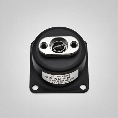
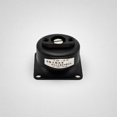
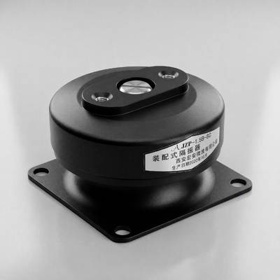
JZP-1.5B-SC as shipped: 46 mm bonded element, zinc-nickel plated insert, laser-etched model and batch code.
Rated load
1.5 kg
Static travel
0.3 mm max.
Axial stiffness
50 N/mm
Natural frequency
10 Hz ±1
Service temperature
-40 to +150 °C
Shock capacity
100 g, 12 cycles
Insert isolation
5 kV AC
Interface
M4 on 40 x 22 mm
Short answer
  • What it is: a single-stud, bonded rubber-to-metal vibration mount of the JZP-B-SC family, made by Xi'an Hoan Microwave Co., Ltd.
  • Load: 1.5 kg rated in compression, 0.3 mm static travel, 50 N/mm axial stiffness.
  • Dynamics: 10 Hz natural frequency, useful isolation from 30 Hz to 500 Hz.
  • Environment: -40 °C to +150 °C continuous with a hybrid compound that resists cold cracking and hot reversion.
  • Durability: 100 g half-sine shock for 12 cycles, 12 J absorbed per event, tensile 12 MPa, tear 40 kN/m.
  • Electrical: 5 kV AC withstand and 1 x 10^9 Ω insulation from insert to insert, 4 mm creepage.
  • Interface: M4 central thread plus four 5.5 mm holes on a 40 x 22 mm pattern, 46 mm diameter, 30 mm tall.

JZP-1.5B-SC Rubber Shock Absorber 46mm Diameter -40°C to +150°C Hybrid Elastomer Body
Envelope and mounting interface
The four-hole base is the reason this model is a drop-in replacement rather than a redesign. Hole pitch, thread size and height match the rest of the family, so an existing bracket does not need rework when a unit is renewed or when the compound is upgraded to the wide-temperature version.
Outline drawing of the JZP-B-SC body
Figure 2. Outline drawing, all dimensions in mm. Third-angle projection; untoleranced sizes follow ISO 2768-mK. The 22 mm pair is measured across the short side of the four-hole pattern.

Dimension table
Symbol Feature Nominal Unit Tolerance
D Body diameter 46 mm ±0.5
H Overall height 30 mm ±1
h Base collar height 21 mm ±0.5
A Hole pitch, long side 40 mm ±0.2
B Base width 50 mm ±0.5
B2 Hole pitch, short side 22 mm ±0.2
d Central thread M4 - 6H - gauge
d2 Clearance hole 5.5 mm +0.2 / 0
R Corner radius 5 mm ±0.5
t Usable thread depth 6 mm min.

 Frequency behaviour: working band versus test envelope
Two frequency statements circulate for this model and they are routinely confused. One describes the span in which the mount is designed to operate. The other describes the span used on the shaker to qualify it. They answer different questions, so they are kept apart here.
Recommended working range
Item Value Unit Engineering basis
Continuous working band 30 - 500 Hz at least 3x the 10 Hz natural frequency
Band with highest attenuation 40 - 200 Hz transmissibility 0.2 or lower on the measured curve
Band to avoid in continuous duty 7 - 15 Hz amplification zone around the natural frequency
Per-unit load window for rated behaviour 1.0 - 1.5 kg keeps natural frequency inside 9 - 11 Hz
Sweep-through during run-up / coast-down transient only - crossing shorter than 3 s, Q stays at or below 2.0

Qualification envelope
Qualification test Level and range Cycles / duration Standard applied
Sine sweep 5 - 50 Hz, 0.5 g peak, 2 oct/min 2 h per axis, 3 axes IEC 60068-2-6 / GB/T 2423.10
Random vibration 10 - 200 Hz, 3.13 g rms 30 min per axis, 3 axes IEC 60068-2-64
Half-sine shock 100 g peak, 6 ms 12 cycles over 6 directions IEC 60068-2-27
Free drop 1.0 m onto rigid steel base, 1.5 kg mass 3 drops per unit, 6 units In-house drop procedure
The familiar 5 - 50 Hz figure belongs to the qualification envelope. Treating it as a service ceiling discards the useful part of the curve: this mount attenuates from 30 Hz upward and remains effective well past 200 Hz.

Curves
Measured transmissibility curve of the JZP-1.5B-SC
Figure 4. Transmissibility versus frequency. Setup: one isolator carrying a 1.5 kg machined steel block, vertical shaker input, 0.5 g peak sine sweep from 5 Hz to 50 Hz at 2 oct/min. Two ICP accelerometers, 10 mV/g, fixed on the base plate and on the block; acquisition at 2 kHz per channel; curve is the mean of three units at 23 °C.
Measured shock response of the JZP-1.5B-SC
Figure 5. Shock response. Setup: 100 g peak, 6 ms half-sine input, 1.5 kg mass, free drop of 1.0 m onto a 200 x 200 x 20 mm steel base; transmitted acceleration and rebound displacement logged at 20 kHz.

Where the curves stop being valid
  • Applies to one isolator excited vertically on a rigid, flat foundation: surface roughness 3.2 µm Ra or finer, flatness 0.1 mm or better.
  • Applies while the carried mass stays between 1.0 kg and 1.5 kg. Heavier or lighter loads move the natural frequency, so the plotted curve cannot be stretched to cover them.
  • In multi-point layouts, divide the supported mass by the number of units and keep each unit inside the 1.0 - 1.5 kg window, then confirm system frequency by test.
  • Not valid for shear, roll or combined loading, for compliant sub-frames, or for panels whose first mode falls between 30 Hz and 200 Hz.
  • The 5 - 50 Hz sweep is a qualification envelope, not a service ceiling; behaviour above 50 Hz is inferred from the compound model and must be re-measured for critical designs.
  • Thermal shift: dynamic stiffness is about 15 % higher at -40 °C and about 20 % lower at +150 °C, moving the natural frequency by roughly ±1.5 Hz.

 Data statement
All figures on this page belong to the released specification of JZP-1.5B-SC and were obtained with the methods stated on the same row. Where a value is typical rather than a released limit it is marked as such. Buyers comparing this mount with alternatives should ask for the same three things: the test rig description, the load used for the frequency figures and the standard behind each strength number. Without them, numbers are not comparable.