logo

products details

Created with Pixso. Home Created with Pixso. Products Created with Pixso.
Rubber Shock Absorber
Created with Pixso.

JZP-1.5B-SC Rubber Shock Absorber 46mm Diameter 1.5kg Static Load 100G Shock Test Dielectric Mount

JZP-1.5B-SC Rubber Shock Absorber 46mm Diameter 1.5kg Static Load 100G Shock Test Dielectric Mount

Brand Name: Hoan
Model Number: JZP-1.5B-SC
MOQ: 4 Pieces
Payment Terms: T/T,L/C,D/A,D/P
Detail Information
Place of Origin:
China
Certification:
ISO 9001:2015
Axial Static Stiffness:
50 N/mm +/-10%
Radial Stiffness:
25 N/mm +/-15%
Natural Frequency:
10 Hz +/-1 Hz Vertical
Dielectric Withstand Insert To Insert:
5 KV AC, 1 Min
Insulation Resistance:
1 X 10^9 Ohm Min.
Field Replacement Threshold:
1 X 10^8 Ohm
Creepage And Clearance:
4 Mm Min.
Highlight:

High Dielectric Isolation Galvanic Corrosion Protection

,

Galvanic Corrosion Protected Zinc Nickel Insert

,

100G Shock Drop Energy Dissipation

Product Description
JZP-1.5B-SC
Insulated Rubber Shock Absorber for Electrically Sensitive Equipment, 1.5 kg Class

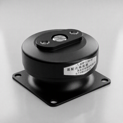
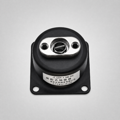
Base view of the JZP-1.5B-SC: four 5.5 mm clearance holes on a 40 x 22 mm pattern and the M4 central insert, both isolated from each other by the elastomer.
Insert-to-insert withstand
5 kV AC
Insulation resistance
1 x 10^9 Ω
Creepage
4 mm min.
Plated insert
zinc-nickel 8-12 µm
Rated load
1.5 kg
Natural frequency
10 Hz ±1
Shock capacity
100 g, 12 cycles
Interface
M4 on 40 x 22 mm
Summary in one screen
  • Purpose: isolate vibration and break the conductive path between an equipment chassis and its support structure.
  • Electrical data: 5 kV AC withstand, 1 x 10^9 Ω insulation resistance, 4 mm creepage, all measured insert to insert.
  • Corrosion data: zinc-nickel plated inserts at 8 - 12 µm, 720 h neutral salt spray without red rust, no bimetallic contact by construction.
  • Mechanical data: 1.5 kg rated load, 0.3 mm static travel, 50 N/mm axial stiffness, 100 g shock for 12 cycles, 12 J absorbed per event.
  • Dynamic data: 10 Hz natural frequency; design band 30 - 500 Hz; 5 - 50 Hz is the qualification sweep only.
  • Thermal data: -40 °C to +150 °C continuous, +160 °C for 30 minutes unloaded, no embrittlement.
  • Envelope: 46 mm diameter, 30 mm high, M4 central thread, four 5.5 mm holes at 40 x 22 mm.

JZP-1.5B-SC Rubber Shock Absorber 46mm Diameter 1.5kg Static Load 100G Shock Test Dielectric Mount

The problem this part addresses
Mounts rarely retire because the rubber wore out. They retire because the mounting stack turned into something else: a rust cell where a steel bolt meets an aluminium frame, a leakage path when condensation bridges two metal faces, or a ground loop that shows up as noise on a measurement channel. A mount that solves only the mechanical half of that problem leaves the other half to be solved with extra parts, extra assembly steps and extra failure points.
JZP-1.5B-SC is designed so that the insulation task and the damping task share one component. A hybrid elastomer element is bonded to a plated steel insert at each end, which means the only path between chassis and support runs through the compound. In one 46 mm part the buyer gets the isolation function, the electrical barrier and the dissimilar-metal separation, on the same 40 x 22 mm anchor pattern already used across the JZP-B-SC family.

 What the insulation data actually says
Electrical figures for a mount are only meaningful when the measurement points and the conditioning are stated. The values below are insert-to-insert, measured on finished parts at 23 °C and 50 % RH after a 24 hour conditioning period.
Property Released value Unit Condition of measurement
Dielectric withstand 5 kV AC 50 Hz, 1 min, no flashover, 4 mm creepage
Insulation resistance 1 x 10^9 Ω 500 V DC, 60 s electrification
Dielectric strength of compound 20 kV/mm IEC 60243-1, 2 mm plaque
Volume resistivity 1 x 10^13 Ω·cm IEC 62631-3-1, 500 V DC
Surface resistivity 1 x 10^12 Ω IEC 62631-3-2, 500 V DC
Creepage and clearance 4 mm shortest surface path, five units measured
Field replacement threshold 1 x 10^8 Ω any reading below this retires the unit
Conditioning matters. The same mount can read below 1 x 10^8 Ω after a night of condensation on a dirty surface. The 4 mm creepage figure assumes a clean, dry surface; where water can pool on the upper face, add a drip shield or re-orient the bracket.

Galvanic protection by geometry, not by coating alone
Coatings slow a galvanic cell down; removing the contact stops it. In this mount the compound physically separates the upper insert from the lower insert, so an aluminium housing bolted to a galvanised frame cannot form a bimetallic couple through the mount.
  • Inserts: steel, zinc-nickel plated 8 - 12 µm over trivalent passivation, 720 h neutral salt spray to ASTM B117 without red rust. A stainless insert version is available for coastal installations.
  • Hardware: plated bolts and, where a bond is required, insulating washers so the fastener does not bridge the two inserts.
  • Surfaces: no copper, brass or bare aluminium is exposed at the interface, which removes the small-area-to-large-area couple that eats bolts on outdoor cabinets.
  • Service: the same geometry keeps the insulation resistance stable in damp conditions, because the corroding couple is not present to begin with.

Mechanical performance in one table
Property Released value Unit Tolerance Verification
Rated load, vertical 1.5 kg ±5 % dead weight, 10 min dwell
Static travel at rated load 0.3 mm max. 0.01 mm indicator
Axial static stiffness 50 N/mm ±10 % load / travel at 1.5 kg
Radial stiffness 25 N/mm ±15 % shear to 5 mm travel
Compression limit 1 : 2 - max. static test, no bottoming
Shock input 100 g peak, 6 ms ±10 % 12 cycles, six directions
Energy absorbed per event 12 J ±10 % 1.0 m drop of 1.5 kg
Permanent set after shock series 0.2 mm max. measured 24 h after test
Tensile strength 12 MPa min. ISO 37
Elongation at break 350 % min. ISO 37
Tear strength 40 kN/m min. ISO 34-1
Bond strength 6 MPa min. ISO 813, 90° peel
Compression set 20 % max. ISO 815-1, 70 h at 100 °C
Hardness 55 Shore A ±5 ISO 7619-1
Unit mass 0.11 kg typical ten units weighed
Design service life 8 years - rated load, indoor 23 °C
The 12 J absorption figure deserves a note: it is the energy taken out of a 1.5 kg mass dropped one metre onto a rigid steel base. That is a handling accident, not a design load, and it is the case where an unprotected board cracks and a protected one does not.


Drawing and interface
Outline drawing of the JZP-B-SC body
Figure 2. Outline drawing, all dimensions in mm. Third-angle projection; untoleranced sizes follow ISO 2768-mK. The 22 mm pair is measured across the short side of the four-hole pattern.

Curves
Measured transmissibility curve of the JZP-1.5B-SC
Figure 4. Transmissibility versus frequency. Setup: one isolator carrying a 1.5 kg machined steel block, vertical shaker input, 0.5 g peak sine sweep from 5 Hz to 50 Hz at 2 oct/min. Two ICP accelerometers, 10 mV/g, fixed on the base plate and on the block; acquisition at 2 kHz per channel; curve is the mean of three units at 23 °C.
Measured shock response of the JZP-1.5B-SC
Figure 5. Shock response. Setup: 100 g peak, 6 ms half-sine input, 1.5 kg mass, free drop of 1.0 m onto a 200 x 200 x 20 mm steel base; transmitted acceleration and rebound displacement logged at 20 kHz.

Data statement
Every number on this page is taken from the released specification for JZP-1.5B-SC and is paired with the method that produced it. Typical values are marked. When comparing offers, request three items: the rig description behind the frequency data, the load used for each dynamic figure, and the standard behind each strength value.