logo

products details

Created with Pixso. Home Created with Pixso. Products Created with Pixso.
Rubber Shock Absorber
Created with Pixso.

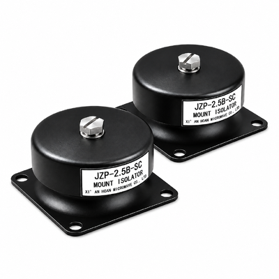
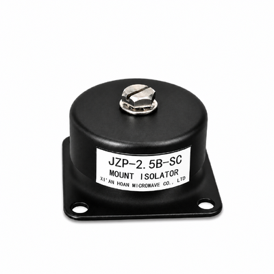
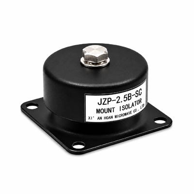
JZP-2.5B-SC Rubber Shock Absorber 2.5kg Rated Load 41.5Hz Resonance M4 Threaded Mount

JZP-2.5B-SC Rubber Shock Absorber 2.5kg Rated Load 41.5Hz Resonance M4 Threaded Mount

Brand Name: Hoan
Model Number: JZP-2.5B-SC
MOQ: 4 Pieces
Payment Terms: T/T,L/C,D/A,D/P
Detail Information
Place of Origin:
China
Certification:
ISO 9001:2015
Product Type:
Rubber-Metal Shock Absorber / Vibration Isolator
Rated Load (kg):
2.5
Static Deflection At Rated Load (mm):
<= 0.3
Natural Frequency (Hz):
41.5 +/- 5 At 2.5 Kg Rated Load
Recommended Operating Frequency:
>= 60 Hz Axial, Transmissibility < 1
Test Sweep Range:
5-50 Hz, 0.5 G Peak, 1 Oct/min
Amplification Band To Avoid:
29-59 Hz
Highlight:

Solvent Swell Resistant Rubber Compound

,

Self-Locking Fastener Anti-Loosening Mount

,

Chemical Resistant Shock Absorber JZP-2.5B-SC

Product Description
MODEL  JZP-2.5B-SC

Rubber Shock Absorber – Solvent-Resistant Body, Self-Locking Fastener Interface

A 2.5 kg rubber-metal isolator for production areas where cutting fluids, hydraulic oil and cleaning solvents attack the elastomer and where vibration slowly backs out the fixing bolts.
Rated load2.5 kg
Natural frequency41.5 ± 5 Hz
Static deflection≤ 0.3 mm
Working temperature-45 … +65 °C
Mounting threadM4
Body sizeØ46 × 30 mm
Short answer. The JZP-2.5B-SC is a 46 mm rubber-metal shock absorber rated at 2.5 kg per mount, with a natural frequency of 41.5 ± 5 Hz and a static deflection of 0.3 mm or less. This version adds a low-swell elastomer that keeps its geometry in oil and solvent contact, plus a self-locking M4 interface that holds preload under continuous vibration. It is used above 60 Hz, where it removes up to 90 % of the transmitted vibration.

Key Facts at a Glance

ModelJZP-2.5B-SC
SeriesJZP-B-SC, 1.0–6.0 kg
BrandHoan
Minimum order4 pieces
Lead time3 days ex stock, 15–25 days production
CertificationISO 9001:2015
OriginChina
Net weightapprox. 0.05 kg

Why the Self-Locking Fastener Interface Matters

Transverse vibration is what loosens bolts. Each cycle lets the joint slip a fraction of a micron, preload decays, and after a few thousand cycles the fixing that was torqued on the line is no longer clamping anything. On a 2.5 kg mount that shows up as a rattle, a shifting cabinet, or an electrical fault that only appears while the machine is running.

What the integrated locking interface provides

  • Preload retention under excitation. The M4 thread pair is built to hold clamp load through continuous dynamic loading, so the joint does not walk loose between service intervals.
  • One less consumable. No thread-locking fluid, no split washer and no secondary retaining strap, which removes an assembly step, a cure time and a quality check per mount.
  • Shock-proven. The interface is qualified together with the body at 100 G for 12 successive shocks, so transport shock and start-stop cycles act on the same joint that was validated.
  • Re-serviceable. The mount can be released and re-fitted during maintenance without destroying the locking feature, which keeps the spare-part number unchanged.

Performance Parameters

Parameter Value Unit Test condition
Rated (nominal) load 2.5 kg Static, axial, 23 ± 2 °C, one mount
Static deflection at rated load ≤ 0.3 mm 2.5 kg load, 23 ± 2 °C, after 3 conditioning cycles
Natural (resonance) frequency 41.5 ± 5 Hz 2.5 kg load, sine sweep 5–50 Hz, 0.5 g peak, 1 oct/min, axial
Recommended operating frequency ≥ 60 Hz Axial, rated load, transmissibility below 1 in this band
Vibration isolation efficiency up to 90 % Axial, ≥ 60 Hz, rated load
Impact resistance 100 G 12 successive shocks, series qualification level
Working temperature -45 to +65 °C Continuous duty, no load derating
Valid period (service life) 8 years Rated load, ≤ 65 °C, normal industrial atmosphere

Frequency Definitions: Recommended Operating Band and Test Sweep Range

Two different numbers describe the frequency behaviour of the JZP-2.5B-SC, and they answer different questions. One tells a designer where the mount may be used; the other only records how the natural frequency was measured during qualification. Mixing them up is a common cause of a mount that appears to amplify vibration instead of reducing it.

RECOMMENDED OPERATING FREQUENCY≥ 60 Hz, axial

Run the mount only above √2 × fn, i.e. 41.5 Hz × 1.414 ≈ 59 Hz, so transmissibility stays below 1 and the mount removes energy instead of storing it. Between 41.5 Hz and 60 Hz the mount sits in its amplification zone and should be avoided. If the disturbance is below 60 Hz, step down to a softer load rating from the same series or change the mounting layout.

TEST SWEEP RANGE5–50 Hz sine sweep

Qualification sweep used to locate fn and confirm the curve: 5–50 Hz, 1 oct/min, 0.5 g peak acceleration, single-axis axial excitation, 2.5 kg load. This is a measurement window for the test house, not a service recommendation.

How to read the three regions of the curve

Region Frequency band for JZP-2.5B-SC What happens Design action
Stiffness-controlled below 29 Hz The mount behaves almost like a rigid joint; deflection is small and little energy is absorbed. Acceptable only when the excitation is well below this band and a rigid path is harmless.
Amplification 29–59 Hz, peak at 41.5 ± 5 Hz Payload motion is larger than base motion; the mount can worsen the problem. Do not operate here. Change load rating, add damping, or redesign the bracket.
Isolation 60 Hz and above Transmissibility falls below 1 and keeps dropping, reaching up to 90 % reduction. Target band. Keep the payload centred and the base stiff.

Technical Data: Curves, Test Conditions, Fixture and Boundaries

JZP-B-SC series outline and mounting dimension drawing
Fig. 1 – Outline and mounting dimensions. D 46 mm, H 30 ± 1 mm, h 21 mm, A 40 ± 0.2 mm, base 50 × 22 mm, M4 internal thread d, Ø5.5 mm anchoring hole d2, R5 fillet. The drawing covers the whole JZP-B-SC series; the 2.5 kg unit differs from its neighbours only in elastomer hardness.
JZP-B-SC series transmissibility curve against frequency
Fig. 2 – Transmissibility against frequency. Test conditions: one JZP-2.5B-SC mount, 2.5 kg payload centred over the upper M4 thread, axial excitation, sweep 5–50 Hz at 0.5 g peak, 1 oct/min, 23 ± 2 °C. Fixture: 10 mm rigid steel base plate with M4 threaded holes at 40 mm centres, payload mass block bolted through the upper thread, one accelerometer on the base plate and one on the payload, single-axis control. Boundary: valid for one mount with a centred mass under axial excitation with a centred payload and the elastomer still within its solvent exposure limits.
JZP-B-SC series impact response curve
Fig. 3 – Impact response. Test conditions: 100 G peak, 12 successive shocks, 2.5 kg payload, same rigid fixture as Fig. 2, room temperature. Boundary: the shock rating applies to one mount loaded axially; more than 12 single-side impacts, off-axis impact, or impact combined with high temperature needs a separate engineering review.
Where the published data stops being valid
  • Values are series qualification data at 23 ± 2 °C; allow ± 10 % batch scatter on natural frequency and on static deflection.
  • Curves assume one mount carrying a centred 2.5 kg mass, loaded axially.
  • In a parallel multi-mount installation, share the load by calculation and keep each mount at or below 2.5 kg; the curve cannot be applied to the assembly as a whole.
  • Shear, roll or inclined mounting changes the stiffness ratio; request direction-specific data before design freeze.
  • Operation above +65 °C, continuous immersion, or an ozone-rich atmosphere shortens the 8-year valid period.
  • Solvent data refers to splash and mist exposure; immersion, vapour-rich enclosures and aromatic or chlorinated solvents must be reviewed separately.

Choosing the Right Load Rating in the Series

All ten models share one drawing. Only the compound hardness changes, which is why the load rating is the only variable a designer has to settle.

Model Rated load (kg) Static deflection (mm) Natural frequency (Hz) Working temperature (°C) Valid period (year)
JZP-1.0B-SC 1.0 ≤ 0.3 41.5 ± 5 -45 to +65 8
JZP-1.5B-SC 1.5 ≤ 0.3 41.5 ± 5 -45 to +65 8
JZP-2.0B-SC 2.0 ≤ 0.3 41.5 ± 5 -45 to +65 8
JZP-2.5B-SC 2.5 ≤ 0.3 41.5 ± 5 -45 to +65 8
JZP-3.0B-SC 3.0 ≤ 0.3 41.5 ± 5 -45 to +65 8
JZP-3.5B-SC 3.5 ≤ 0.3 41.5 ± 5 -45 to +65 8
JZP-4.0B-SC 4.0 ≤ 0.3 41.5 ± 5 -45 to +65 8
JZP-5.0B-SC 5.0 ≤ 0.3 41.5 ± 5 -45 to +65 8
JZP-5.5B-SC 5.5 ≤ 0.3 41.5 ± 5 -45 to +65 8
JZP-6.0B-SC 6.0 ≤ 0.3 41.5 ± 5 -45 to +65 8

Selection in four steps

  1. Add the equipment mass to the bracket mass to get the total payload.
  2. Divide by the number of mounts, then apply 1.2–1.5 as a dynamic margin for start-stop and transport loads.
  3. Round down to the nearest rating in the table: a 2.2 kg result stays on JZP-2.5B-SC, a 2.7 kg result moves up to JZP-3.0B-SC.
  4. Check the excitation frequency against the 29–59 Hz amplification band; if the disturbance sits there, change the layout or the rating rather than accepting the mount.

Storage, Service and End of Life

  • Storage: keep in the original bag, away from direct sunlight, ozone sources such as electric motors, and solvent vapours; 10–30 °C and below 70 % RH. The 8-year valid period counts from commissioning, not from the production date.
  • Inspection: check preload and elastomer appearance every 12 months, or every 6 months above +50 °C. Look for cracking at the fillet, permanent set, or a shiny contact line between rubber and metal.
  • Replacement: replace when static deflection has grown visibly, when the rubber shows cracks deeper than the fillet radius, or after a shock event above the 100 G qualification level.
  • End of life: the aluminium base and the steel insert are separated from the elastomer and go to normal metal recycling; the compound carries no halogenated plasticiser.


Send the fluid, the payload mass and the excitation frequency

We will confirm whether JZP-2.5B-SC holds the duty, or answer with the correct load rating from the same series within one working day.