logo

products details

Created with Pixso. Home Created with Pixso. Products Created with Pixso.
Rubber Shock Absorber
Created with Pixso.

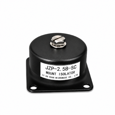
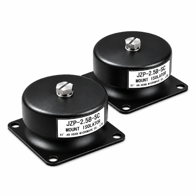
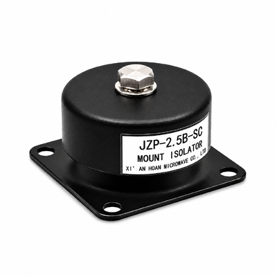
JZP-2.5B-SC Rubber Shock Absorber 46mm Body 30mm Height 0.3mm Static Deflection -45C to +65C

JZP-2.5B-SC Rubber Shock Absorber 46mm Body 30mm Height 0.3mm Static Deflection -45C to +65C

Brand Name: Hoan
Model Number: JZP-2.5B-SC
MOQ: 4 Pieces
Payment Terms: T/T,L/C,D/A,D/P
Detail Information
Place of Origin:
China
Certification:
ISO 9001:2015
Anchoring Hole D2:
Dia 5.5 Mm, For M5 Fixing
Net Weight:
Approx. 0.05 Kg
Elastomer:
Low-carbon, Non-halogenated Compound Without Plasticiser
Mounting Type:
Threaded, Bolt-on, Upright, Inverted, Wall Or Inclined
Service Life:
8 Years
Series Range:
JZP-B-SC, 1.0-6.0 Kg
Application:
Wall Mounted Cabinets, Ceiling Hung Sensors, Inclined Camera Mounts
Highlight:

360 Degree Omnidirectional Damping Isolator

,

Flexible Spatial Mounting Shock Absorber

,

Low Carbon Footprint Eco Elastomer

Product Description
MODEL  JZP-2.5B-SC

Rubber Shock Absorber – 360-Degree Omnidirectional Damping, Low-Carbon Elastomer

A 2.5 kg rubber-metal isolator that dampens all the way round its body, so the same part works upright, inverted, on a wall or on an incline, built from a compound without plasticiser and with a reduced process carbon footprint.
Rated load2.5 kg
Natural frequency41.5 ± 5 Hz
Static deflection≤ 0.3 mm
Working temperature-45 … +65 °C
Mounting threadM4
Body sizeØ46 × 30 mm
Short answer. The JZP-2.5B-SC is a 46 mm rubber-metal shock absorber rated at 2.5 kg per mount, with a natural frequency of 41.5 ± 5 Hz and a static deflection of 0.3 mm or less. Its elastomer body generates damping around the full 360° circumference, so one part number covers vertical, inverted, wall and inclined mounting, and the compound is a low-carbon formulation without plasticiser. It is used above 60 Hz, where it removes up to 90 % of transmitted vibration.

Key Facts at a Glance

Part numberJZP-2.5B-SC
FamilyJZP-B-SC, 1.0–6.0 kg
MakerHoan
Smallest order4 pieces
Availability3 days ex stock, 15–25 days production
Quality systemISO 9001:2015
OriginChina
Mass per pieceapprox. 0.05 kg

What the Part Is and How It Works

The JZP-2.5B-SC is an elastomer body vulcanised between a metal base and a threaded face. Energy arriving from the machine frame is taken up as strain in the compound, converted to a small amount of heat by internal friction, and returned to the equipment at a far lower level than a rigid joint would pass through.

It is the 2.5 kg member of a ten-model family from 1.0 kg to 6.0 kg, all built on the same 46 × 30 mm drawing. Because the envelope and the hole pattern are shared, a load change late in the project costs a part number change, not a bracket redesign.

How 360-Degree Damping Opens Up the Mounting Layout

Conventional isolators are tuned for one axis. The engineer picks a vertical or a horizontal part, then builds the frame around that choice, and a cabinet that ends up on a wall needs a second bracket to stop it rocking. The JZP-2.5B-SC works differently: the elastomer body is deflected in compression and in shear at the same time, all the way round the circumference, so the restoring force is balanced whichever way the mount is turned.

What that means in practice

  • Four mounting positions, one part. Upright, inverted, on a vertical wall or on an inclined bracket: the M4 thread in one face and the two Ø5.5 mm anchoring holes in the other stay reachable, so nothing has to be re-machined to suit a new frame geometry.
  • No stabilising bracket. Because radial stiffness is balanced, a side-mounted cabinet does not rock about the fixing line and does not need a second support to stop it.
  • Fewer part numbers. One rating covers the horizontal, vertical and angled positions in the same machine, which simplifies the drawing, the pick list and the maintenance store.
  • Predictable retrofit. Replacing a rigid foot with this mount does not force a change of hole pattern: 40 mm centres and an M4 central thread fit many existing footprints.
What to recalculate when the axis changes
  • The 2.5 kg rating is an axial figure; in side mounting only the component along the mount axis counts against it.
  • Radial stiffness is higher than axial stiffness, because the compound works mainly in shear in that direction.
  • The published curves are measured axially and stay a design reference, not a substitute, for inclined installations.

The Low-Carbon Elastomer Formulation

Isolator compound is usually judged on stiffness, and the process behind it is ignored. That process is where the carbon sits: the vulcanisation route, the plasticiser package and the scrap rate all add embodied emissions to a 50 g part that is bought by the thousand. This formulation was revisited on all three counts without giving up the 8-year valid period.

Three changes, one compound

Change What it does Effect on the installation
Reduced-energy vulcanisation route Lower process energy per batch for the same cure state Lower embodied carbon per piece, no change to stiffness or life
Package without plasticiser No migrating oil to bloom out of the compound No oily film on the frame, no volatile release inside a closed cabinet
Non-halogenated, declared materials Compound can be disclosed item by item Feeds directly into a customer carbon or material declaration

Long life is the largest saving

Over 8 years at rated load, the environmental cost of a mount is dominated by how many times it is replaced and shipped, not by the 50 g of material. Fewer change-outs means fewer cartons, fewer shipments and less downtime per machine, which is why the service life is part of the environmental case rather than a separate sales point.

Dimensional Parameters

Dimension Symbol Value Unit Tolerance Measurement condition
Outside diameter D 46 mm series drawing Calliper check at 23 ± 2 °C, unloaded
Overall height H 30 mm ± 1 Calliper check at 23 ± 2 °C, unloaded
Elastomer body height h 21 mm series drawing Reference dimension, unloaded
Hole centre distance A 40 mm ± 0.2 Across both anchoring holes, base face
Base plate width B 50 mm series drawing Unloaded, base face
Base plate thickness B 22 mm series drawing Unloaded, base face
Threaded mounting hole d M4 - 6H Internal thread in the upper face
Anchoring through hole d2 Ø5.5 mm H12 Takes an M5 base fixing bolt
Fillet radius R 5 mm series drawing Elastomer body fillet

Frequency: Working Band and Test Sweep Kept Separate

The same part carries two frequency figures, and they are not interchangeable: one is an instruction to the installer, the other is a note from the test house. Confusing them is how a correctly made mount ends up amplifying the very vibration it was bought to remove.

RECOMMENDED WORKING FREQUENCY60 Hz and above, axial

Set the working point clear of √2 × fn. With fn at 41.5 Hz that boundary lands at 59 Hz, so 60 Hz is the entry point of the useful band: from there upward transmissibility drops below 1 and the body starts dissipating instead of storing. A disturbance that lives between 41.5 Hz and 60 Hz needs a different rating or a different bracket, not a softer foot.

TEST SWEEP RANGE5–50 Hz, 0.5 g, 1 oct/min

This is the sweep the laboratory runs over a 2.5 kg payload to find fn and plot the curve: single-axis, axial, sine, one octave per minute. It records where resonance sits; it does not say the mount should be operated anywhere inside it.

Reading the body’s behaviour across the range

  • Below 29 Hz the body is stiff compared with the excitation: it acts close to a solid spacer, moves very little and absorbs very little.
  • Between 29 Hz and 59 Hz the payload sits on the wrong side of resonance and motion grows instead of shrinking — the signature of a mount that was chosen for load but not for frequency.
  • From 60 Hz upward the response decays steadily and the part does its job, reaching up to 90 % less transmitted motion.

Test Data: Curves, Fixture, Conditions and Limits

Every figure below was measured on the series sample set rather than calculated, so the conditions belong with the numbers.

Outline drawing of the JZP-B-SC rubber shock absorber with mounting dimensions
Drawing 1 – Outline and fixing geometry. 46 mm outside diameter, 30 ± 1 mm overall height, 21 mm body height, 40 ± 0.2 mm between the anchoring holes, 50 × 22 mm base, M4 internal thread, Ø5.5 mm through holes, R5 fillet. One drawing serves all ten ratings; the 2.5 kg unit differs only in compound hardness.
Transmissibility curve of the JZP-B-SC series over the sweep band
Drawing 2 – Transmissibility over the sweep band. How it was measured: one mount, 2.5 kg mass centred on the upper thread, axial sine sweep 5–50 Hz, 0.5 g peak, 1 oct/min, 23 ± 2 °C. Rig: a 10 mm steel plate with M4 holes on 40 mm centres, the mass block bolted through the upper thread, one accelerometer on the plate and one on the block, single-axis control. Limits: the curve belongs to one mount under axial excitation with a centred mass and axial excitation; in inclined or side mounting the curve remains a design reference and the radial stiffness correction must be applied.
Impact response of the JZP-B-SC series
Drawing 3 – Impact response. How it was measured: 100 G peak, 12 shocks in succession, 2.5 kg mass, same rig as Drawing 2, room temperature. Limits: the shock figure covers one axially loaded mount; a thirteenth impact, an off-axis blow, or impact at elevated temperature falls outside the qualification and needs a separate review.
Limits of the published figures
  • Measured on the series sample set at 23 ± 2 °C; production parts vary by about ± 10 % on natural frequency and static deflection.
  • One mount, 2.5 kg centred mass, axial direction. Nothing else.
  • Four mounts in parallel are four separate single-mount cases: split the load by calculation and keep each at or under 2.5 kg.
  • Turn the mount to shear, roll or an incline and the stiffness ratio changes; ask for the direction-specific data before the layout is signed off.
  • Beyond +65 °C, in permanent immersion, or in an ozone-rich enclosure, the eight-year period shortens.
  • Omnidirectional damping is a property of the body shape; every published curve is still measured axially and must be corrected for radial or inclined service.

Stock, Inspection and Disposal

  • Stock: keep in the original bag, out of sunlight and away from ozone sources such as running motors and solvent vapours; 10–30 °C, below 70 % RH. The eight-year period starts at commissioning, not at the production date.
  • Inspection: 12-monthly, or 6-monthly where the ambient stays above +50 °C. Watch the fillet for cracks, the base for permanent set, and the rubber-metal line for a glossy separation mark.
  • Replacement trigger: visible growth in static deflection, cracks deeper than the R5 fillet, or a shock event beyond the 100 G qualification level.
  • Disposal: the aluminium base and the steel insert separate from the compound and go to metal recovery; the compound carries no halogenated plasticiser.


Send the mounting orientation, the payload mass and the excitation frequency

We will confirm the axial share for your installation and return the correct rating from the same series within one working day.