logo

products details

Created with Pixso. Home Created with Pixso. Products Created with Pixso.
Rubber Shock Absorber
Created with Pixso.

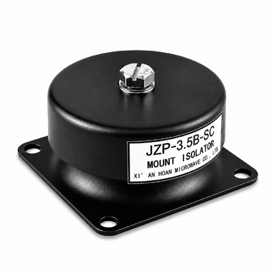
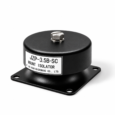
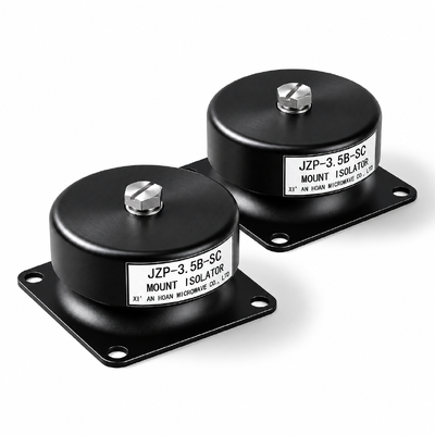
JZP-3.5B-SC Rubber Shock Absorber 3.5kg Load 41.5Hz Resonance ESD-Safe Conductive Elastomer Marine Subsea Grade

JZP-3.5B-SC Rubber Shock Absorber 3.5kg Load 41.5Hz Resonance ESD-Safe Conductive Elastomer Marine Subsea Grade

Brand Name: Hoan
Model Number: JZP-3.5B-SC
MOQ: 4 Pieces
Payment Terms: T/T,L/C,D/A,D/P
Detail Information
Place of Origin:
China
Certification:
ISO 9001:2015
Shock Endurance:
100 G / 6 Ms, 12 Cycles, 3 Axes
Outer Diameter X Height:
46 Mm X 30+/-1 Mm
Mounting:
M4 Insert, Phi 5.5 Mm Clearance Hole, A40+/-0.2 X B50 Mm, 2.0 N.m Torque
Unit Mass:
0.2 Kg
Service Life:
8 Years Continuous Duty
Application:
Electronics Assembly Static Control, Marine Deck And Subsea Housings
Highlight:

ESD-Safe Conductive Elastomer

,

Salt Spray Resistant Marine Mount

,

Hydrostatic Pressure Qualified

Product Description
JZP-3.5B-SC
ESD-Safe Conductive Elastomer Rubber Shock Absorber for Electronics Assembly and Marine Equipment
Rated load3.5 kg per mount
Surface resistance104 to 106 Ω
Salt spray500 h, ASTM B117
Hydrostatic1.0 MPa, 30 min
Working range-45 ~ +65 °C
Quick answer

The JZP-3.5B-SC in this version is a 46 mm metal-rubber mount carrying 3.5 kg per mount at a 41.5 ± 5 Hz resonant frequency, with an elastomer compounded to a carbon network that holds surface resistance between 104 and 106 ohm. Static charge on the isolated structure drains to the frame through the mount body instead of building up and discharging into a board or a connector. The same part is qualified through 500 h of neutral salt spray to ASTM B117 and a 1.0 MPa hydrostatic hold for 30 minutes, so it keeps its damping after exposure to salt air and after a pressure test equivalent to roughly 100 m of water depth.

Key facts

Item Value
Model designation JZP-3.5B-SC
Product type Cylindrical metal-rubber mount with dry friction damping and conductive elastomer
Rated vertical load 3.5 kg per mount (34.3 N)
Static deflection at rated load ≤0.30 mm, tolerance ±0.05 mm
Resonant frequency 41.5 ± 5 Hz
Surface resistance 104 to 106 Ω, static dissipative band
Volume resistivity ≤104 Ω·cm
Charge decay, 1,000 V to 100 V Under 2 s at 12% relative humidity
Isolation band (rated operation) 60 Hz to 2,000 Hz
Salt spray 500 h neutral fog, ASTM B117
Damping shift after salt fog ±5% or less
Hydrostatic hold 1.0 MPa for 30 min, no leakage
Operating temperature -45 °C to +65 °C
Envelope and mass Φ46 mm × 30 mm high, 0.2 kg
Service life 8 years in continuous duty at rated load

Three functions carried by one part

  • Charge drainage. A conductive carbon network runs through the elastomer, so the mount behaves as a controlled resistor between payload and frame rather than as an insulator. Resistance stays high enough to avoid a hard short and low enough to bleed charge away in well under a second under normal handling conditions.
  • Vibration attenuation above 60 Hz. Isolation comes from the same dry friction mechanism as the rest of the family, dissipated as low-grade heat at the bonded interface. Adding the conductive filler changes the electrical behaviour; the damping shift measured after exposure stays inside ±5%.
  • Wet and saline service. The insert is plated and the bond line is fully encapsulated, so salt fog does not reach the metal-rubber interface and start the under-film corrosion that shortens the life of ordinary rubber mounts.

Dimensions and mounting interface

Symbol Dimension Value Tolerance Unit How it is measured
D Body outer diameter 46 - mm Unloaded, 23 ± 2 °C
H Overall height, unloaded 30 ±1 mm Unloaded, 23 ± 2 °C
h Elastomer section height 21 - mm Unloaded, 23 ± 2 °C
A Mounting hole pitch, long side 40 ±0.2 mm Centre to centre, unloaded
B Mounting hole pitch, short side 50 - mm Centre to centre, unloaded
d Threaded insert M4 - - Go / no-go gauge
d2 Clearance hole Φ5.5 - mm Pin gauge, unloaded
R Corner radius 5 - mm Profile projector
b Base plate thickness 22 - mm Unloaded
JZP-3.5B-SC dimension drawing

M4 threaded insert on the load side, Φ5.5 mm clearance hole on the frame side, 40 ± 0.2 mm by 50 mm pitch. Recommended fastener torque 2.0 N·m. The frame contact area must be bare, conductive metal: paint, anodising, powder coat or an insulating gasket in the load path breaks the electrical drain and leaves the assembly floating again.

Frequency ratings: working band and test sweep range are separate figures

Recommended working band — operating rating
60 Hz to 2,000 Hz
Derived from √2 × 41.5 Hz = 58.7 Hz, rounded up to 60 Hz. In this band the mount attenuates rather than amplifies, with the highest attenuation at the upper end. Continuous running in the 36 Hz to 47 Hz window around the resonance is excluded, and the same exclusion applies after salt fog exposure because the damping shift stays inside ±5%.
Test sweep range — qualification only
5 Hz to 2,000 Hz
Sine sweep at 0.5 g, 1 oct/min, single-axis base excitation, performed twice: as-new and again after the 500 h ASTM B117 exposure. Sweep data below 60 Hz is diagnostic and is not an operating capability of the part.
Two limits worth stating plainly. The 1.0 MPa hydrostatic hold qualifies the mount body under pressure; it does not turn the mount into a pressure boundary or a sealing element. Splash-zone mounting also needs a shield against direct wave impact, because the qualification covers continuous fog and a static pressure hold, not repeated dynamic wave loading.

Performance curves, test conditions and fixture

JZP-B-SC series vibration transmissibility curve
Figure 1 – Transmissibility against excitation frequency, JZP-B-SC series.
Test conditions: sine sweep 5–2,000 Hz, constant 0.5 g input, 1 oct/min, single-axis vertical base excitation, 23 ± 2 °C, 50% relative humidity, unit at 3.5 kg. The plotted run is taken after 500 h of neutral salt spray so that the curve reflects service condition rather than the as-new state.
Fixture description: steel platen not thinner than 25 mm on an electro-dynamic shaker; four M4 inserts at 2.0 N·m; control accelerometer on the platen under the unit centreline, response accelerometer on the 3.5 kg payload plate. The platen is bare zinc-plated steel so the electrical path during the run matches the installed condition, and body-to-frame resistance is logged before and after the sweep.
Boundary of validity: applies to a single unit carrying a centred vertical load of 3.5 kg in a sheltered marine atmosphere. Immersion beyond the 30-minute 1.0 MPa hold, continuous splash, or load applied through the side wall is outside the qualified envelope.
JZP-B-SC series impact response curve
Figure 2 – Impact response, JZP-B-SC series.
Test conditions: half-sine pulses of 100 G peak, 6 ms duration, 12 consecutive events per axis, three orthogonal axes, unit pre-loaded at 3.5 kg, 23 ± 2 °C.
Fixture description: drop-test machine with a rigid aluminium fixture block; four M4 inserts at 2.0 N·m; accelerometer on the block above the unit centreline. Electrical continuity between payload plate and base plate is checked before and after the pulse train to confirm the conductive path survives shock.
Boundary of validity: one pulse train at peak acceleration up to 100 G. Repeated random shock above that level, shock arriving through the elastomer side wall, or impact while the unit is unloaded all fall outside the qualified envelope.

Installation and continuity verification

  1. Confirm the frame pad is bare conductive metal and flat within 0.1 mm across the 40 × 50 mm footprint.
  2. Fit the mount at 2.0 N·m, tightening diagonally in two passes. Do not place an insulating washer, plastic bush or rubber gasket between the base plate and the frame.
  3. After installation, measure resistance from the payload plate to the frame with an ohmmeter on the 106 ohm range; a reading at or below 106 ohm confirms the drain path is intact.
  4. Record the four foot gaps and the continuity reading as the commissioning baseline.
  5. Repeat the continuity check after any maintenance that involves loosening a fastener, and after any incident that loads the mount in shear.

Storage, inspection and service life

  • Store between 5 °C and 35 °C, below 70% relative humidity, out of direct sunlight and away from ozone sources such as running motors.
  • Keep the conductive surfaces clean; solvent wipe is acceptable, silicone spray and release agents are not, because they leave an insulating film on the drain path.
  • Annual inspection: bond line, insert threads, foot gaps against baseline, and resistance from payload plate to frame.
  • Replace when the foot gap drifts more than 0.10 mm from baseline, when resistance rises above 106 ohm after cleaning, when a bond-line crack reaches the load-bearing section, or at the end of the 8-year design life.

Ordering information

Supplied individually with M4 insert and Φ5.5 mm clearance hole on a 40 ± 0.2 mm by 50 mm pitch, in an antistatic bag with desiccant and an individual carton. Sets of four with matched static deflection are available for level-critical installations. Minimum order is 4 pieces. Delivered 7 to 15 working days after payment, with 20,000 pieces per month available.