logo

products details

Created with Pixso. Home Created with Pixso. Products Created with Pixso.
Rubber Shock Absorber
Created with Pixso.

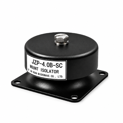
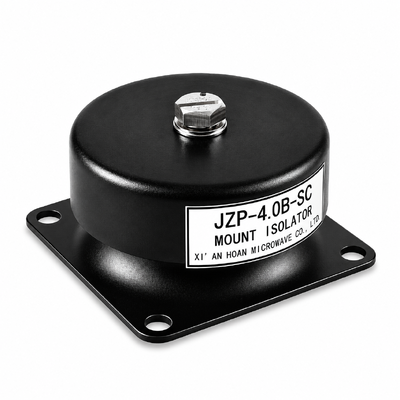
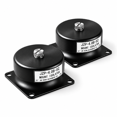
JZP-4.0B-SC Rubber Shock Absorber 4.0kg Rated Load 41.5Hz Damping Ratio 0.13 Fast Settling Mount

JZP-4.0B-SC Rubber Shock Absorber 4.0kg Rated Load 41.5Hz Damping Ratio 0.13 Fast Settling Mount

Brand Name: Hoan
Model Number: JZP-4.0B-SC
MOQ: 4 Pieces
Payment Terms: T/T,L/C,D/P,D/A
Detail Information
Place of Origin:
China
Certification:
ISO 9001:2015
Rated Vertical Load:
4.0 Kg Per Mount
Lateral To Vertical Stiffness:
0.5 To 0.7 Typical For This Bonded Geometry
Clamp Load At 2.0 N.m:
2.4 To 2.6 KN Typical On Clean Dry M4 Threads
Mass:
0.2 Kg
Design Life:
8 Years Continuous Duty
Mounting Plans:
3 Points 12 Kg, 4 Points 16 Kg, 4 Plus 2 Outriggers 24 Kg
Highlight:

High Loss Factor Elastomer Damping

,

Fretting Corrosion Control Metal Interface

,

Fast Settling Rubber Shock Absorber

Product Description
JZP-4.0B-SC
Rubber Shock Absorber with High Loss Factor Elastomer for Fast Settling and Fretting-Resistant Interfaces
Rated load4.0 kg per mount
Resonance41.5 ± 5 Hz
Static deflection≤0.30 mm
Damping ratio≥0.13
Temperature-45 ~ +65 °C
Short answer

The JZP-4.0B-SC is a 46 mm diameter bonded rubber-to-metal shock absorber that carries 4.0 kg per mount, resonates at 41.5 ± 5 Hz, and deflects 0.30 mm or less at its rating. It is built around a high loss factor elastomer whose measured damping ratio is 0.13 or above, which is what separates it from a plain resilient pad: motion left over from an impact dies out in roughly 110 ms instead of several hundred.

The second half of the design is the fixing interface. Both faces that contact metal — the M4 insert on the load side and the Ø5.5 mm clearance seat on the frame side — carry a bonded dry-film lubricant, and the insert is chemically bonded into the elastomer rather than pressed into it. The intent is to stop contact micro-slip at the screw joint before it turns into fretting corrosion and loose preload.

Damping in three measurements: why the ringing stops early

Damping is easy to claim and hard to verify, so it is stated here in the three forms a test house can actually produce. The damping ratio of 0.13 comes from the width of the transmissibility peak. The logarithmic decrement of 0.82 is its time-domain twin from a decay trace with the payload released. The settling time of 110 ms is what those two numbers mean to a machine builder waiting for motion to stop before the next move.

Behaviour This element, ζ 0.13 Plain resilient compound, ζ 0.05 Consequence on the machine
Amplitude removed per cycle about 44% about 27% Fewer cycles to reach the same quiet state
Cycles to 5% of initial amplitude about 4.5 about 9.5 Decay ends in half the oscillatory events
Settling time at 41.5 Hz 110 ms 230 ms Shorter dead time before the next commanded move
Peak at resonance 3.85x 10x Smaller excursion during run-up and run-down
Floor under high-band attenuation higher floor lower floor The trade: settling speed is bought with some upper-band attenuation

That last row is the honest cost of the grade. Where a design needs the deepest possible attenuation at several hundred hertz and can tolerate a longer ring-down, the standard compound suits it better. Where the axis must be still before the next command, the high loss factor version wins the argument.

Fretting corrosion: the failure that hides under a tight screw

A joint can be correctly torqued, visually sound and still be failing. Two clamped faces under vibration slide against each other by micrometres; the protective oxide is rubbed off, bare metal oxidises, the layer is rubbed off again. The end state is a ring of reddish powder around the fastener, a preload that has quietly dropped, and a mount that feels loose for no visible reason.

Three features of the JZP-4.0B-SC work against that sequence:

  • Dry-film lubricant on both seats. A bonded MoS2 layer on the M4 insert and on the base seating face holds the friction pair stable, so the faces slide instead of galling and the preload does not wander. A dry film is used on purpose: oil would migrate into the bonded joint and attract dust, while grease would change the pair the coating was chosen for.
  • A bonded, keyed insert. The thread is bonded and mechanically keyed into the elastomer, not pressed in. A pressed bush can rock under cyclic load, and rocking is what opens the clearance that starts fretting. Pull-out is qualified at 500 N or more.
  • Interface pressure held in a defined window. The 40 ± 0.2 mm by 50 mm pattern and the 22 mm seat width spread the clamp load over a known footprint. Kept inside roughly 3 to 8 MPa at the seat, the joint tolerates micro-slip of up to about 150 µm through a 106-cycle test without producing through-thickness oxide debris.

Reading the joint in service

What you see What it means What to do
Fine reddish or dark powder ring at the screw seat Active fretting; the protective film has been broken Clean the seat, confirm flatness and re-torque; check that no washer was added
Torque falls away at the annual check Preload lost to wear or to elastomer creep Re-torque once to 2.0 N·m; if it falls again within a year, replace the element
Shiny polished patch on the base plate Sliding contact, not the intended clamped contact Re-check that the fixing screw is the specified grade and fully seated
Gap under one foot grows by more than 0.10 mm Creep or a damaged bond line Replace the element; do not compensate with a thicker shim alone
Hairline crack reaching the load-bearing section Bond-line separation Replace immediately; the joint strength is no longer defined
Assembly discipline. No plain washer stack, no rubber gasket, no thread-locking fluid at these two seats. Each one changes the friction pair the coating was selected for, and a soft gasket in particular turns the joint back into a micro-slip generator. Fit the element to bare, degreased metal and torque the M4 screw to 2.0 N·m.

How many mounts, and how much load each one sees

Load per mount, not total payload, is the number that selects the element. Dividing total mass by the count is valid as long as the centre of gravity sits inside the polygon formed by the fixing points; outside it, the nearest mount carries more than its share.

Mounting plan System capacity at this rating When it is the right answer
Three points 12 kg Rigid triangular frame, light payload, levelling easy with shims
Four points, rectangular 16 kg Standard layout for cabinets, benches and machine bases
Four points plus two outriggers 24 kg Long or tall payload where rocking is the concern

Worked check. A 14 kg bench on four elements loads each one to 3.5 kg, a little under the 4.0 kg rating and comfortably inside the 3.6 to 4.4 kg band the transmissibility curve was taken in. The same bench on three elements loads each to 4.67 kg, which is over the rating: the elastomer will bottom out on shock and the curve no longer applies. Either add a fourth foot or step up to the JZP-5.0B-SC. Keep the centre of gravity inside the mounting rectangle and keep any single element between 3.6 kg and 4.4 kg, and the published numbers hold without correction.

Environment, media and life expectancy

  • Temperature. Rated for continuous duty from -45 to +65 °C. Vertical stiffness shifts by roughly 10% across that window, which moves the resonance by about 5%; a design that sits close to the 60 Hz crossover warrants a temperature sweep rather than an assumption.
  • Oils and coolants. The compound resists incidental contact with mineral oil, cutting fluid and glycol coolant. Continuous immersion, chlorinated solvents and brake fluid are outside the rating and need a shield or a different compound.
  • Outdoor exposure. Ozone and ultraviolet are the two ageing mechanisms that matter. Keep the element out of direct sun and away from motors, which generate ozone, and expect a shorter life outdoors than the 8-year indoor figure.
  • Storage. 5 to 35 °C, below 70% RH, away from sunlight, motors and solvent vapours. Shelf life is 5 years in the original packaging, after which the compound should be re-checked before use.
  • Inspection. Once a year: bond line, insert threads, and the four foot gaps against the values recorded at commissioning. Drift beyond 0.10 mm, a crack reaching the load-bearing section, or the 8-year mark is the replacement trigger, whichever comes sooner.

Fixing positions and dimensional envelope

Feature Size Tolerance Note
Body outer diameter, D 46 mm - Measured unloaded at 23 ± 2 °C
Overall height, H 30 mm ±1 Unloaded, before load is applied
Elastomer section height, h 21 mm ±0.5 Rubber block between the two steel faces
Hole pitch, lengthwise, A 40 mm ±0.2 Centres of the two fixing positions
Hole pitch, crosswise, B 50 mm ±0.2 Base plate length on the same axis
Load-side thread, d M4 6H Bonded insert, not a pressed bush
Frame-side hole, d2 Ø5.5 mm +0.2 / 0 Clearance hole for the fixing screw
Base plate corner radius, R 5 mm - Rounded to avoid a stress riser
Base plate width 22 mm ±0.2 Seating face available for clamping
JZP-4.0B-SC outline drawing with fixing positions

The load side carries an M4 bonded insert; the frame side carries a Ø5.5 mm clearance hole on a 40 ± 0.2 mm by 50 mm pitch. Seat flatness should be 0.1 mm or better across that footprint. A warped seat bends the base plate and pushes bending stress into the bonded joint, which shortens life long before the elastomer itself ages. Tighten diagonally in two passes so the plate is not pre-bent.

Rating bands: running capability and qualification window kept apart

These two numbers are routinely quoted as if they were the same thing. One states how the part may be run; the other states where it was tested.

Recommended working band — how the part is rated to run
60 Hz to 2,000 Hz
At the 41.5 Hz resonance multiplied by √2 the transmissibility crosses unity at 58.7 Hz, so 60 Hz is the next whole number above the crossover. Everything above it is attenuated rather than amplified, and the attenuation deepens as frequency climbs. The 36 Hz to 47 Hz window, which contains the 41.5 ± 5 Hz resonance, is excluded from the running rating.
Test sweep range — how the part was qualified
5 Hz to 2,000 Hz
Swept sine at 0.5 g and one octave per minute, driven through the base. The sweep has one job: find the resonance and record the transmissibility trace. Data below the 60 Hz crossover inside that sweep is diagnostic output, not a statement about how the element may be run.
Selection note. Identify the dominant disturbance of the equipment before choosing an element. Motors, gearboxes, blowers and chiller compressors sit above 60 Hz and fall inside the rated band. A 25 to 40 Hz disturbance needs a softer solution altogether; changing the bolt pattern will not move the resonance far enough.

Performance curves, with rig and validity limits

Vertical transmissibility of the JZP-B-SC element across 5 to 2000 Hz
Curve A – vertical transmissibility, JZP-B-SC element at the 4.0 kg rating.
Conditions: swept sine, 5 Hz to 2,000 Hz, held at 0.5 g, one octave per minute, single axis through the base, 23 ± 2 °C, 50% RH, payload 4.0 kg.
Rig: a steel platen of at least 25 mm thickness bolted to an electro-dynamic shaker. The element is fixed through all four M4 inserts at 2.0 N·m. A control accelerometer is bonded to the platen beneath the element centreline; a response accelerometer is bonded to a simulated payload plate whose mass equals the 4.0 kg rating, so the peak on the plot corresponds to a correctly loaded unit.
Where the curve stops applying: one element, one centred vertical load of 4.0 kg. A load offset, two elements in series, a payload outside 3.6 to 4.4 kg, or excitation fed in through the side wall each move the curve and need a separate qualification sweep.
Shock response of the JZP-B-SC element under half-sine pulses
Curve B – shock response, JZP-B-SC element.
Conditions: half-sine pulses, 100 G peak, 6 ms duration, twelve consecutive pulses on each of three orthogonal axes, element pre-loaded to 4.0 kg, 23 ± 2 °C.
Rig: drop machine with a rigid aluminium fixture block. The element is bolted through all four M4 inserts at 2.0 N·m and the accelerometer is bonded to the block above the element centreline. Insert pull-out and the bonded joint are re-checked after the pulse train.
Where the curve stops applying: a single pulse train up to 100 G peak. Random shock above that level, shock entering through the elastomer wall rather than the base plate, or an impact taken while the element is unloaded sits outside the qualified envelope.

Ordering and packing

Each element ships in a protective bag in its own carton, with the M4 insert and Ø5.5 mm clearance hole on the 40 ± 0.2 mm by 50 mm pitch as standard. Matched sets of four are packed together with the deflection record so the set stays together through transport. Minimum order is 4 pieces, delivery is 7 to 15 working days after payment, and monthly capacity is 20,000 pieces. Non-silicone, low-outgassing compound options are available on request for cleanroom and optical builds; state the requirement on the order so the compound is selected before production rather than after.