logo

products details

Created with Pixso. Home Created with Pixso. Products Created with Pixso.
Rubber Shock Absorber
Created with Pixso.

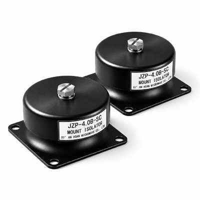
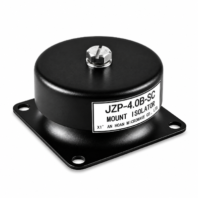
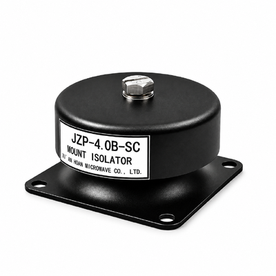
JZP-4.0B-SC Rubber Shock Absorber 46mm Stackable Series Architecture 0.25 Rebound Ratio Modular Mount

JZP-4.0B-SC Rubber Shock Absorber 46mm Stackable Series Architecture 0.25 Rebound Ratio Modular Mount

Brand Name: Hoan
Model Number: JZP-4.0B-SC
MOQ: 4 Pieces
Payment Terms: T/T,L/C,D/P,D/A
Detail Information
Place of Origin:
China
Certification:
ISO 9001:2015
Operating Temperature:
-45 To +65 C, Stiffness Drift About 10 Percent Across The Window
Body Diameter X Height:
46 Mm X 30 Mm (H +/-1); Series Pair 60+/-2 Mm
Mass:
0.2 Kg Per Element
Design Life:
8 Years Continuous Duty
Application:
Frames With Late Changes In Disturbing Frequency, Transport-mounted Equipment, Drop And Shock Protection
Highlight:

Stackable Series Stiffness Adjustment

,

Low Rebound Impact Energy Absorption

,

Modular On-Site Stroke Tuning Mount

Product Description
JZP-4.0B-SC
Stackable Rubber Shock Absorber with On-Site Stiffness and Stroke Adjustment and Low Rebound Energy Absorption
Rated load4.0 kg per mount
Body / height46 mm / 30 mm
Stiffness272 N/mm, 136 N/mm stacked
Rebound ratio0.25 max
Temperature-45 ~ +65 °C
Short answer

The JZP-4.0B-SC is a 46 mm diameter, 30 mm high bonded rubber-to-metal shock absorber rated at 4.0 kg per mount with a 41.5 ± 5 Hz resonance. Its two fixing faces share one 40 × 50 mm pattern, which lets two elements bolt back to back: a series pair halves vertical stiffness to about 136 N/mm, doubles usable stroke to 0.60 mm and lowers the resonance to about 29 Hz, with no change to the frame footprint.

The compound is formulated for hysteresis rather than spring-back. Drop rebound measurements put the coefficient of restitution at 0.25 or below, so a payload leaves the element at no more than a quarter of the speed it arrived with, and the second bounce peaks below 6.3% of the original drop height. The impact is absorbed once instead of being handed back in instalments.

Technical data, stated with the condition that produced it

The table describes one element at its rated point. Stacking changes stiffness, stroke and installed height; it does not change load capacity, which is covered separately below.

Parameter Rating Tolerance Unit Basis of the figure
Rated vertical load, Pz 4.0 - kg Static load held 24 h at 23 ± 2 °C before reading
Static deflection under Pz 0.30 max ±0.05 mm Rigid platen, 24 h dwell, dial indicator resolved to 0.01 mm
Usable stroke, one element 0.30 - mm Travel before the elastomer bottoms, equal to the deflection at rating
Vertical stiffness, one element, derived 272 - N/mm k = (2πf)2m from 41.5 Hz and 4.0 kg
Resonance, one element 41.5 ±5 Hz Swept sine 5 to 2,000 Hz, 0.5 g, one octave per minute, base driven
Resonance, two in series, derived 29.3 - Hz From the halved stiffness at the same 4.0 kg payload; confirm by sweep before release
Damping ratio 0.13 min - ratio Half-power width of the transmissibility peak, 4.0 kg payload
Coefficient of restitution 0.25 max - ratio 300 mm drop onto a rigid platen, ratio of rebound to arrival velocity
Arrival velocity at 300 mm drop, derived 2.43 - m/s √(2gh); the payload leaves at 0.61 m/s or less
Energy returned on rebound 6.3 max - % e2 with e = 0.25; above 93% is dissipated in the elastomer
Series elements without an external guide 2 max - element Vertical compression builds; a third element needs a guide pin
Spacer ring heights 3 / 5 / 8 ±0.1 mm Stainless ring between elements; sets height, not stiffness
Shock withstand 40 - g at 11 ms Half-sine pulse, element at rated load
Shock endurance 100 - G at 6 ms Twelve pulses per axis on three axes, base mounted
Overturning check at 40 g, derived 1.57 - kN 4.0 kg × 9.81 × 40; check this against the stack height to size a guide
Operating temperature -45 to +65 - °C 2 h soak at each limit, reading repeated after return to 23 °C
Body diameter × height 46 × 30 H ±1 mm Unloaded at 23 ± 2 °C; two stacked measure 60 ± 2 mm
Mass 0.2 - kg As packed, insert included
Design life 8 - year Continuous duty at 4.0 kg inside -45 to +65 °C, clean industrial air

Stiffness is a decision you can still make on site

Disturbing frequencies are often confirmed after the frame is welded, and by then the mount has usually been ordered. This element is built so the installed stiffness can be changed with a torque wrench instead of a drawing revision: two identical units in series behave as two springs in series, giving half the stiffness and twice the stroke, and the load-side insert of one unit threads into the frame-side hole of the next, so no adapter plate is needed.

Build Vertical stiffness Stroke available Resonance at 4.0 kg Installed height Load per mount
One element 272 N/mm 0.30 mm 41.5 Hz 30 mm 4.0 kg
Two in series 136 N/mm 0.60 mm 29.3 Hz 60 mm 4.0 kg
Two in series with 5 mm ring 136 N/mm 0.60 mm 29.3 Hz 65 mm 4.0 kg
Two in parallel, one foot 544 N/mm 0.30 mm 58.7 Hz 30 mm 8.0 kg
Rules the stacking method depends on. A series stack is stable in vertical compression and nowhere else. Two elements without a guide is the limit; a third needs a pin that takes the lateral load, because an unguided stack of three leans, and a leaning stack has a resonance that changes with amplitude. Spacer rings change height and nothing else — they are a levelling aid, not a tuning device. Series stacking adds stroke and reduces stiffness; it does not add load capacity.

Worked example. A 16 kg instrument sits on four single elements at 4.0 kg each and resonates at 41.5 Hz. A pump added to the same frame introduces 33 Hz, which falls in the region where a single element amplifies rather than isolates. Two elements per foot drop the installed resonance to about 29 Hz and move the 33 Hz line out of that region, with no change to the frame or the bolt pattern. Re-rate the working band after the change: a two-element stack is rated from about 45 Hz upward, which is √2 × 29.3 Hz.

Environment, media and life expectancy

  • Temperature. Continuous duty from -45 to +65 °C. Vertical stiffness shifts by roughly 10% across the window, which moves the resonance by about 5%; a stack already close to its crossover deserves a temperature sweep rather than an assumption.
  • Oils and coolants. Incidental contact with mineral oil, cutting fluid and glycol coolant is acceptable. Continuous immersion, chlorinated solvents and brake fluid are outside the rating and need shielding or a different compound.
  • Outdoor exposure. Ozone and ultraviolet drive the ageing. Keep the element out of direct sun and away from motors that generate ozone, and expect a shorter life outdoors than the 8-year indoor figure.
  • Storage. 5 to 35 °C, below 70% RH, away from sunlight, motors and solvent vapours. Shelf life is 5 years in the original packaging.
  • Inspection. Once a year: bond line on each element in the stack, insert threads, stack alignment, and the foot gaps against the commissioning baseline.
JZP-4.0B-SC outline drawing with fixing positions

The same pattern appears on the upper and lower faces — M4 bonded insert on the load side, Ø5.5 mm clearance hole on the frame side, 40 ± 0.2 mm by 50 mm pitch — and that symmetry is what allows back-to-back stacking without an adapter. Apply 2.0 N·m to every joint in a stack, not just the one at the frame.

Rating bands: running capability and qualification window kept apart

The two figures below answer different questions and are often quoted as one. The upper figure describes how the element may be run; the lower one describes where it was tested.

Recommended working band — how the part is rated to run
60 Hz to 2,000 Hz
At the 41.5 Hz resonance multiplied by √2 the transmissibility crosses unity at 58.7 Hz, so 60 Hz is the next whole number above the crossover. Everything above it is attenuated rather than amplified, and the attenuation deepens as frequency climbs. The 36 Hz to 47 Hz window, which contains the 41.5 ± 5 Hz resonance, is excluded from the running rating.
Test sweep range — how the part was qualified
5 Hz to 2,000 Hz
Swept sine at 0.5 g and one octave per minute, driven through the base. The sweep has one job: find the resonance and record the transmissibility trace. Data below the 60 Hz crossover inside that sweep is diagnostic output, not a statement about how the element may be run.
Note for stacked builds. The band above describes one element. In a series pair the resonance falls to about 29 Hz, so the rated band starts at 45 Hz instead of 60 Hz, while the qualification sweep stays at 5 to 2,000 Hz. Quote the band that matches the build actually shipped, and label the shipped configuration on the packing list.

Performance curves, with rig and validity limits

Vertical transmissibility of the JZP-B-SC element across 5 to 2000 Hz
Curve A – vertical transmissibility, JZP-B-SC element at the 4.0 kg rating.
Conditions: swept sine, 5 Hz to 2,000 Hz, held at 0.5 g, one octave per minute, single axis through the base, 23 ± 2 °C, 50% RH, payload 4.0 kg.
Rig: a steel platen of at least 25 mm thickness bolted to an electro-dynamic shaker. The element is fixed through all four M4 inserts at 2.0 N·m. A control accelerometer is bonded to the platen beneath the element centreline; a response accelerometer is bonded to a simulated payload plate whose mass equals the 4.0 kg rating, so the peak on the plot corresponds to a correctly loaded unit.
Where the curve stops applying: one element, one centred vertical load of 4.0 kg. A load offset, two elements in series, a payload outside 3.6 to 4.4 kg, or excitation fed in through the side wall each move the curve and need a separate qualification sweep.
Shock response of the JZP-B-SC element under half-sine pulses
Curve B – shock response, JZP-B-SC element.
Conditions: half-sine pulses, 100 G peak, 6 ms duration, twelve consecutive pulses on each of three orthogonal axes, element pre-loaded to 4.0 kg, 23 ± 2 °C.
Rig: drop machine with a rigid aluminium fixture block. The element is bolted through all four M4 inserts at 2.0 N·m and the accelerometer is bonded to the block above the element centreline. Insert pull-out and the bonded joint are re-checked after the pulse train.
Where the curve stops applying: a single pulse train up to 100 G peak. Random shock above that level, shock entering through the elastomer wall rather than the base plate, or an impact taken while the element is unloaded sits outside the qualified envelope.

Ordering and packing

Elements ship individually in a protective bag inside their own carton; pre-assembled two-element stacks are crated upright so the stack is not side-loaded in transit, and spacer rings are packed separately. State on the order whether you need single elements, pre-assembled stacks, or a matched set of four with a deflection spread of 0.10 mm or less, so the set is measured together rather than picked from stock. Minimum order is 4 pieces, delivery is 7 to 15 working days after payment, and monthly capacity is 20,000 pieces.